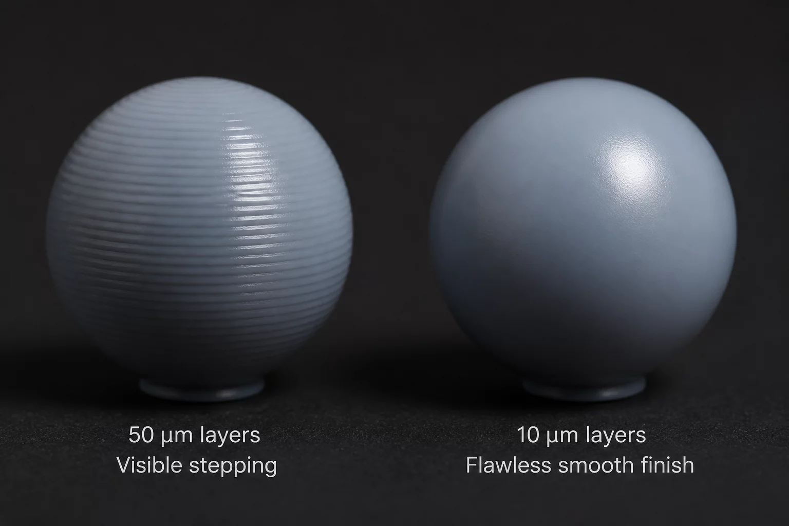
In resin 3D printing, achieving perfectly smooth curves presents a significant challenge due to the digitized nature of additive manufacturing. Every model is sliced into discrete layers along the Z-axis, creating physical steps along curved or angled surfaces. This technical brief examines how layer height directly influences this stepping phenomenon, how the print angle affects step visibility, and how anti-aliasing can be used to mitigate surface artifacts.
The Mechanics of Stair-Stepping on Sloped Surfaces
The visible stepping effect, often called stair-casing, is a direct consequence of representing a continuous mathematical curve with flat, horizontal planes. The horizontal width of each step on a sloped surface depends on two factors: the layer height and the angle of the surface relative to the build plate. As the surface slope approaches horizontal (angles close to 0° relative to the build platform), the step width increases dramatically, making the layers highly visible to the naked eye. Conversely, near-vertical surfaces exhibit minimal Z-axis stepping but are more susceptible to pixelation from the LCD screen's X/Y resolution.
Comparative Analysis: 50μm, 25μm, and 10μm Layers
To quantify the visual and structural impact of Z-axis resolution, we conducted tests using a standard 50mm sphere printed at different layer configurations using a high-resolution monochrome LCD printer:
- 50 Microns (0.05mm): Highly visible stepping is apparent on the upper dome of the sphere, where the surface angle is shallow. Post-processing requires significant sanding, which can alter the dimensional accuracy of the part.
- 25 Microns (0.025mm): The stepping is greatly reduced. The steps are visible under direct lighting but feel relatively smooth to the touch. This setting offers the best balance between print time and surface quality for most organic miniatures.
- 10 Microns (0.010mm): The surface appears completely smooth to the naked eye. Stepping is only detectable under magnification. However, printing times are increased by 400% compared to 50-micron prints, and the risk of print failure due to peel forces is higher.
The Role of Anti-Aliasing and Voxel Smoothing
While reducing layer height addresses Z-axis stepping, pixelation along the X/Y axes can still cause micro-stepping on curved profiles. Slicing software like CHITUBOX uses anti-aliasing algorithms to apply grey levels to boundary pixels. This grey-scaling partially cures the resin at the outer edges, creating a transitional zone that smooths out the steps. When combined with a optimized layer height (such as 30 microns), anti-aliasing can produce surfaces that rival injection-molded plastics without the excessive print times of ultra-thin layers.
Optimal Strategies for Printing Curved Geometries
To achieve the best possible surface finish on curved parts, we recommend the following protocol:
- Orient curved surfaces at an angle between 30° and 60° relative to the build plate to minimize the horizontal projection of Z-steps.
- Select a layer height between 25 and 35 microns for a balanced ratio of quality to print speed.
- Enable Anti-Aliasing with a grey level set to 4 or 8 to soften pixel boundaries without losing fine detail.
Add Your Perspective